Auxiliary equipment & integrated systems
e-mail [email protected] Language EN ES

Equipment

Ribbon Blender

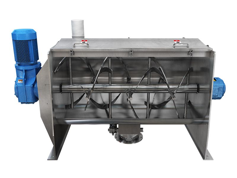
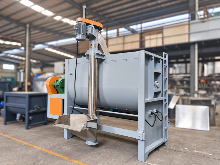
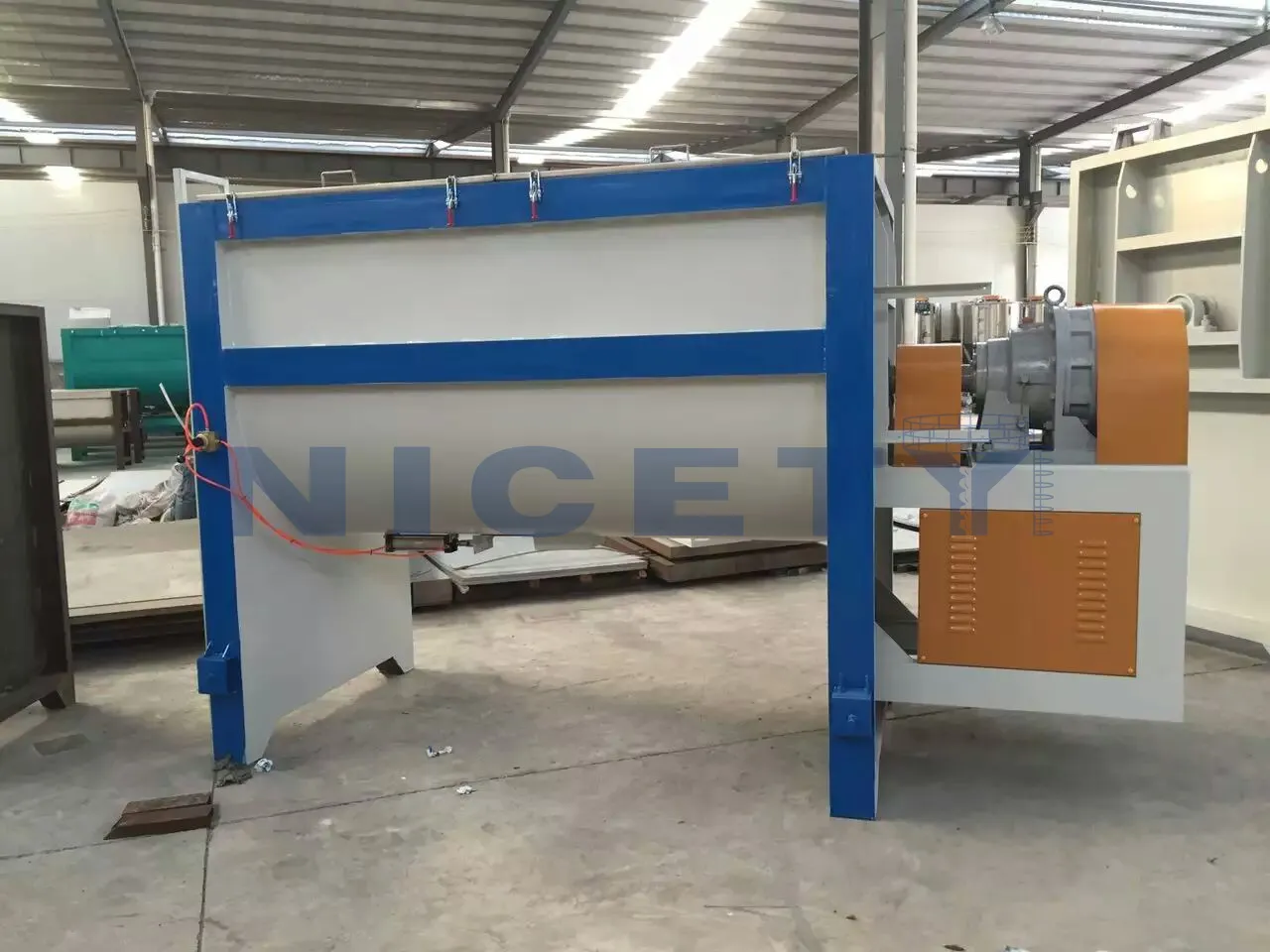
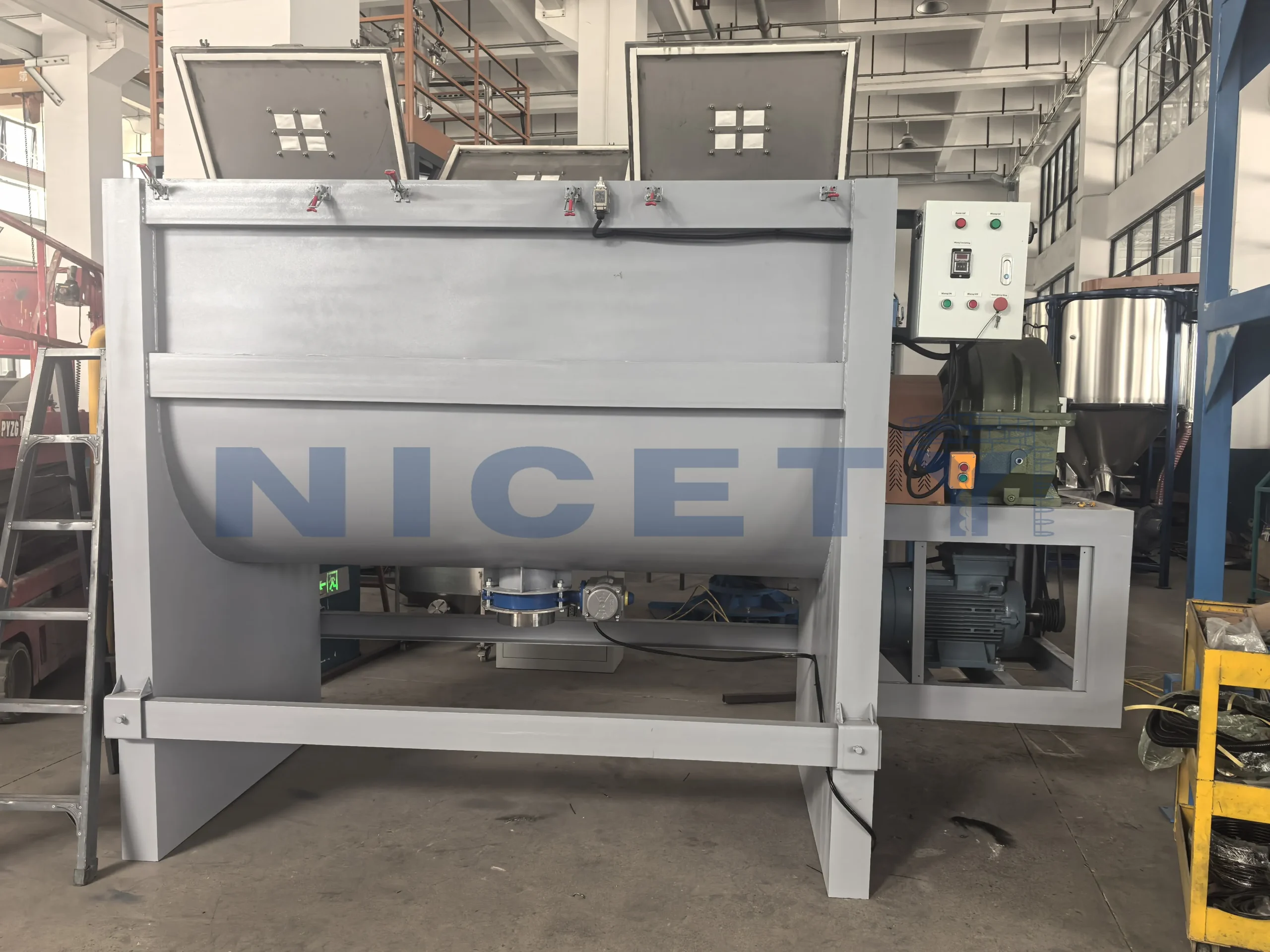
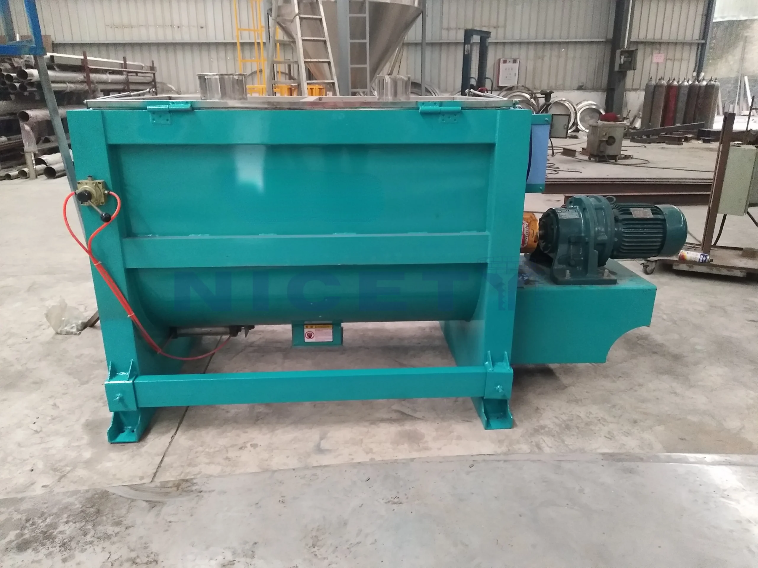
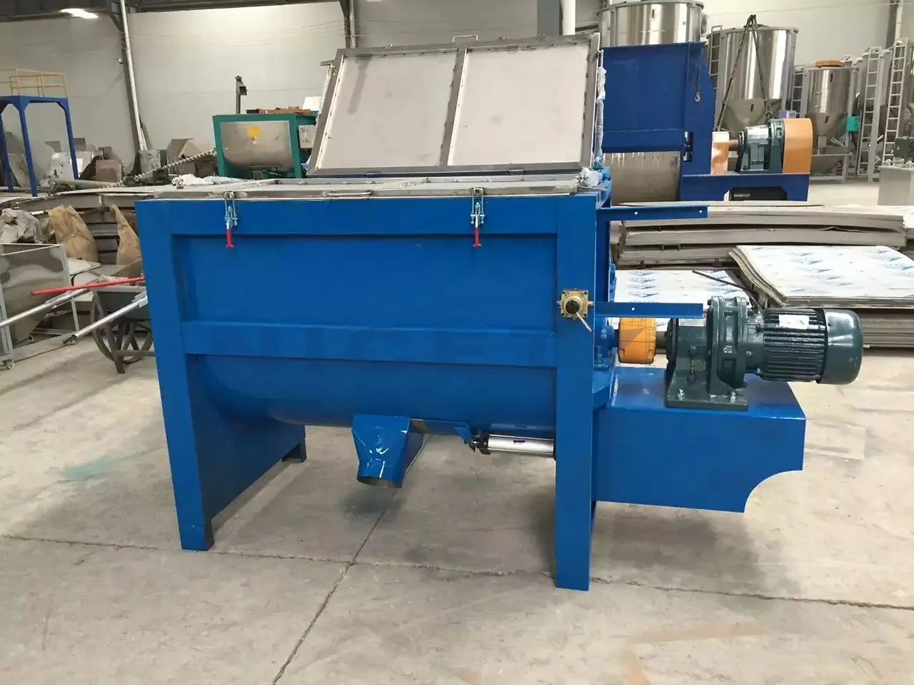
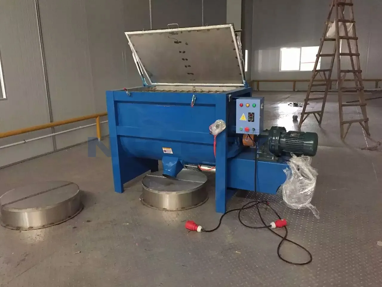
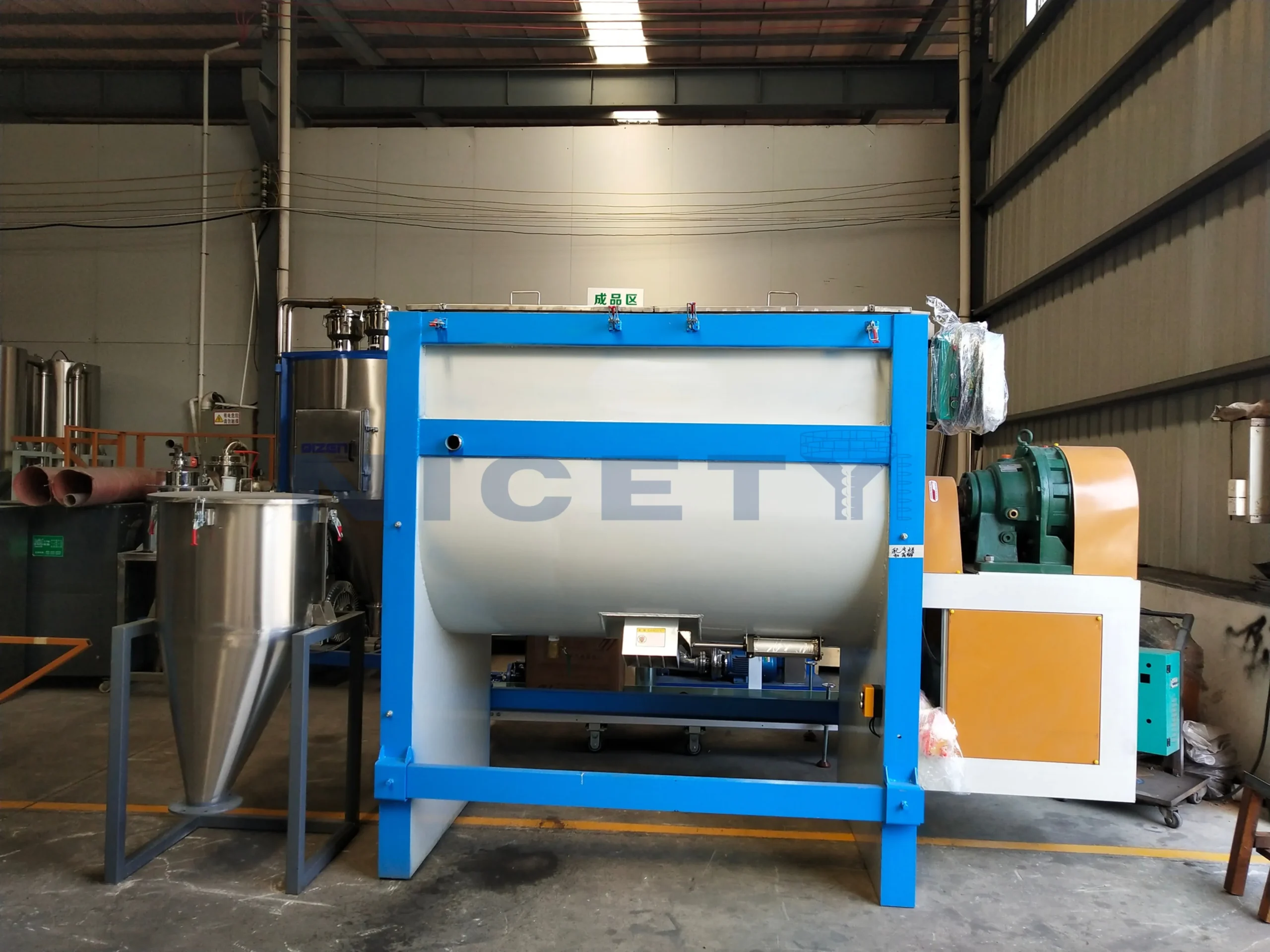
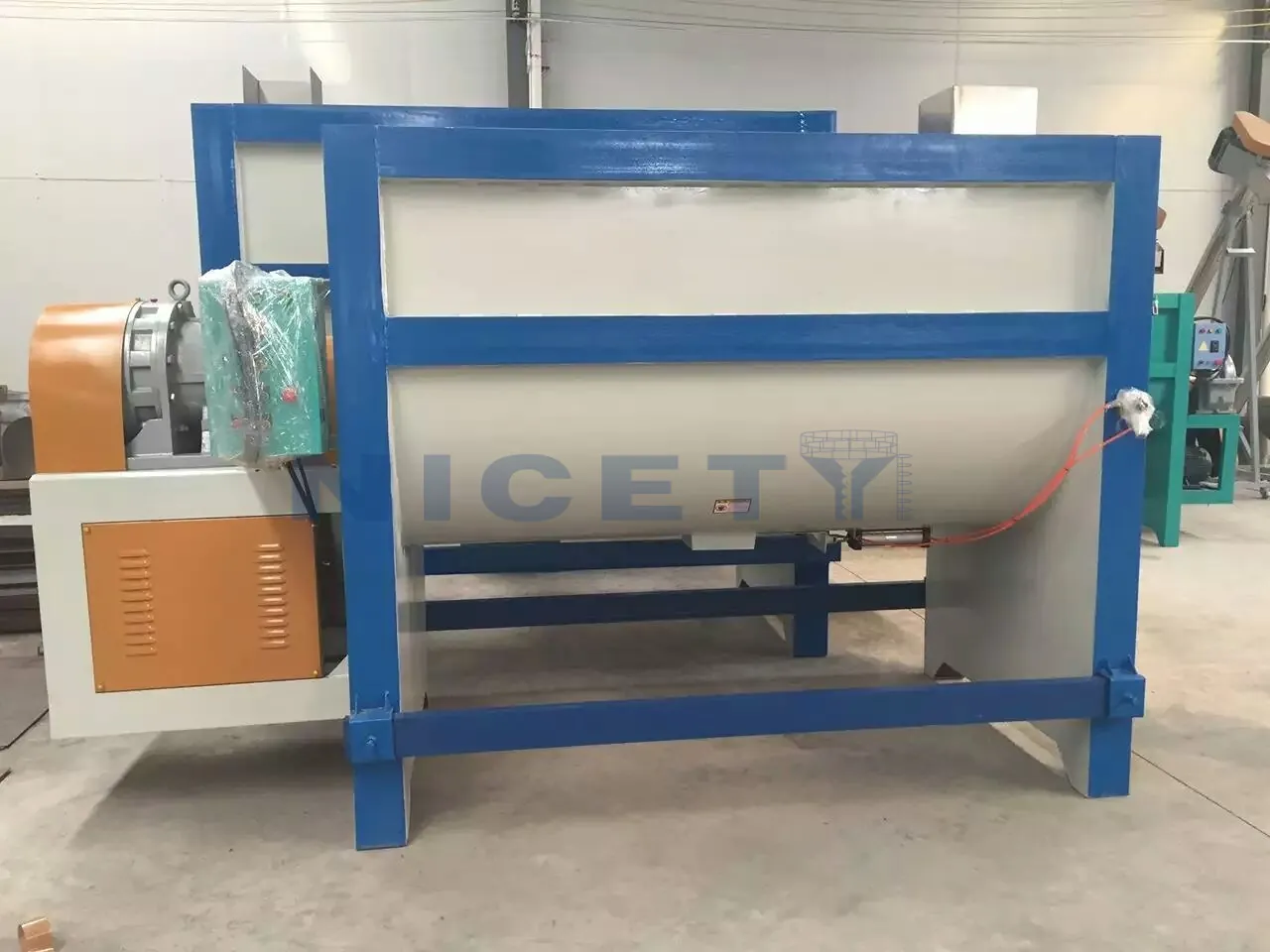
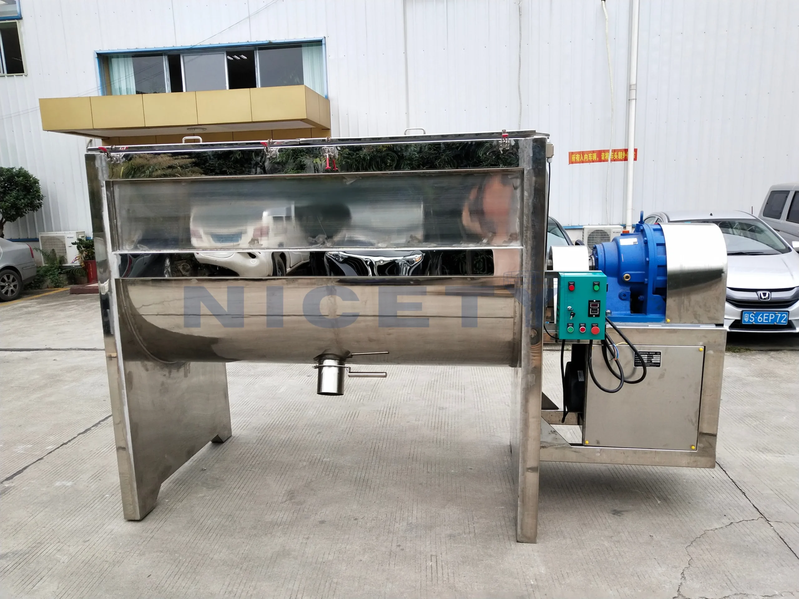
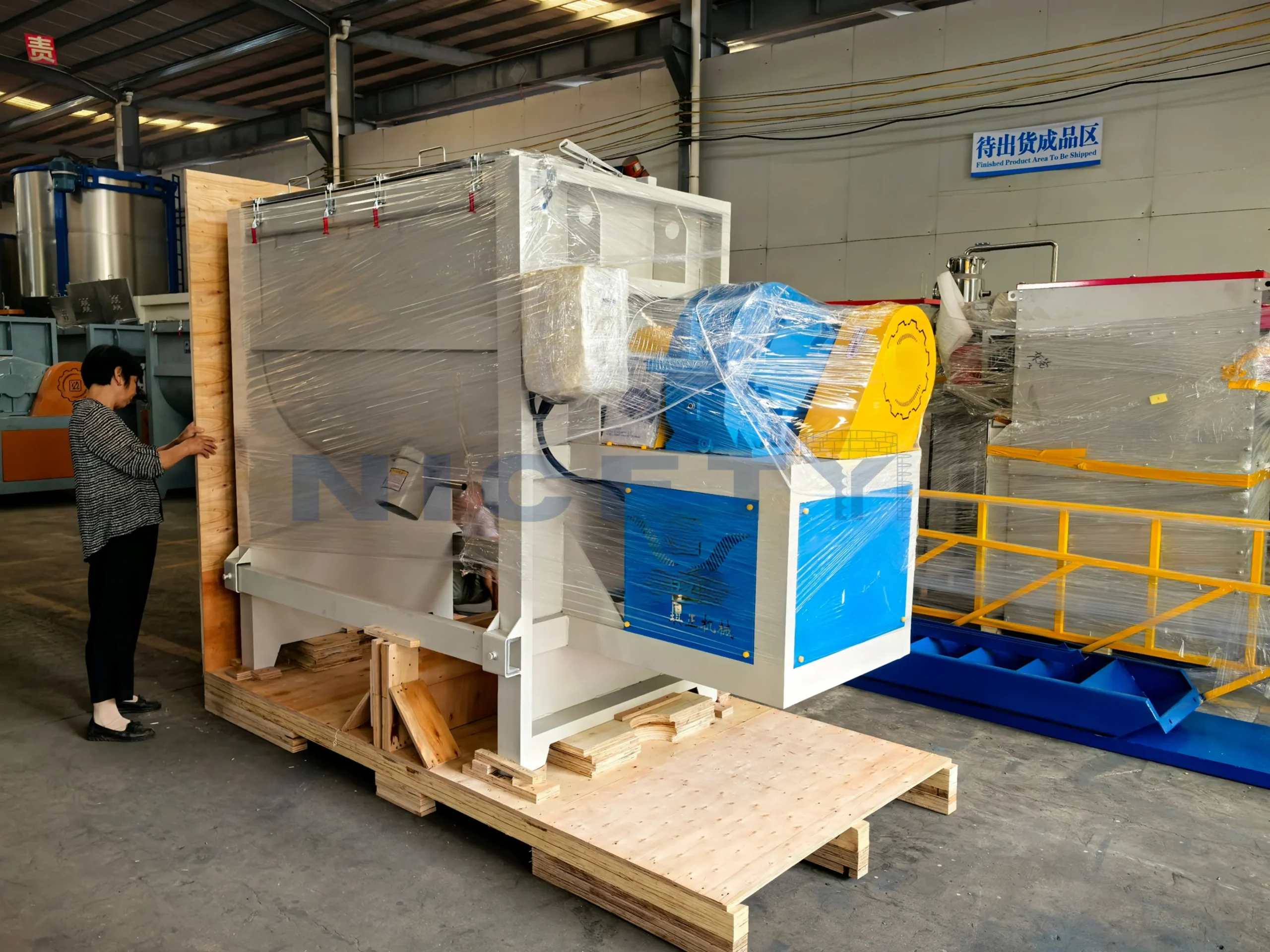
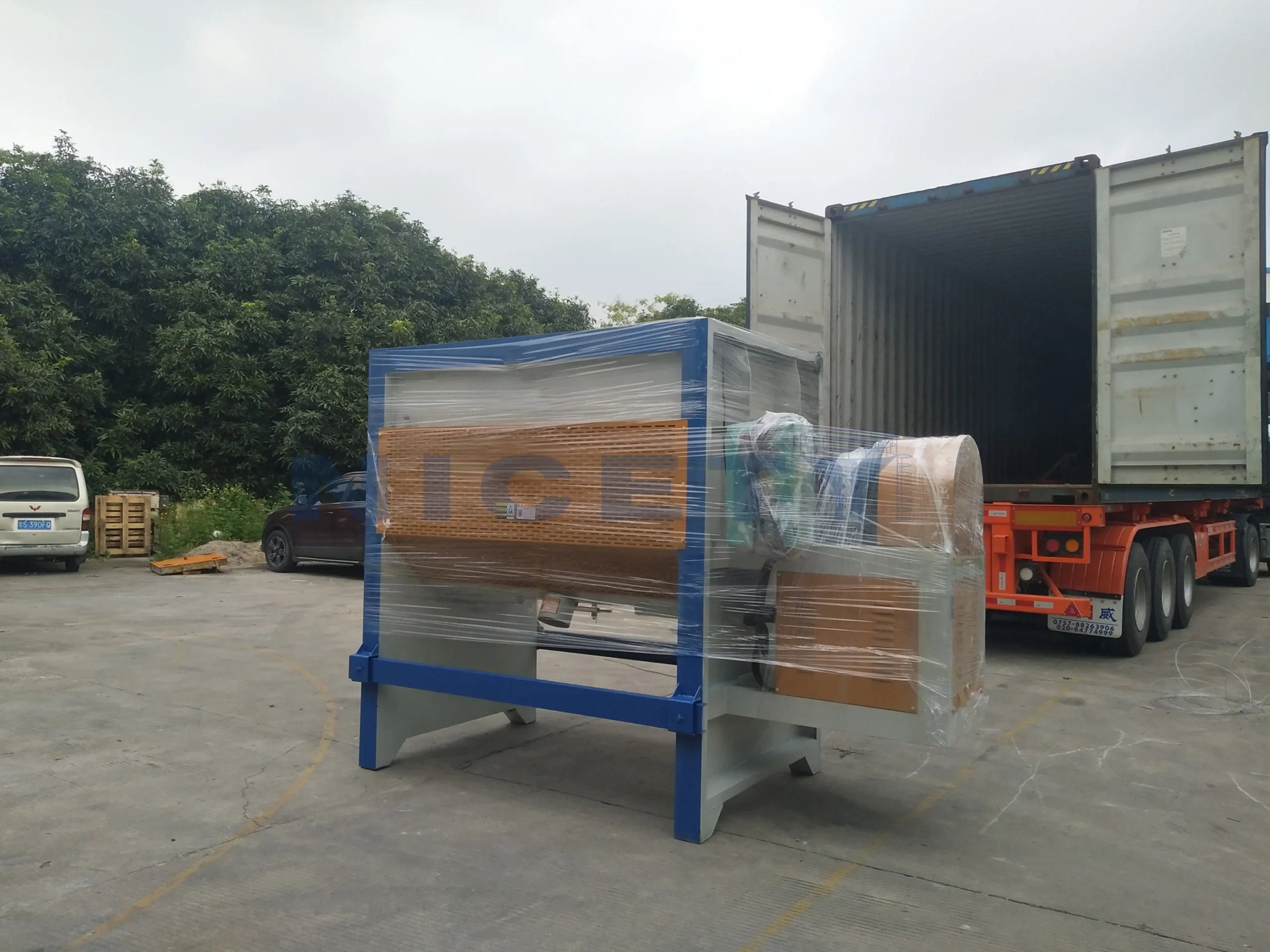
Horizontal ribbon blender with counter-flow double helical ribbons for convective batch blending of polymer pellets, powders, regrind, and masterbatch without frictional heat build-up.

  • Mixing and Homogenizing Equipment
  • Mixing
  • Post-Pellet Treatment
  • Raw Material Preparation
  • Modified Plastics
  • Multifunctional Masterbatch
  • Resin
  • Rubber
  • Thermoplastic Elastomer
  • TPE
  • TPU
  • Pellets
  • Powder
  • Batch-to-batch variation
  • Uneven additive distribution
Capacity range
300–10000 L (batch working volume)
Models
NC-W200 · NC-W300 · NC-W500 · NC-W1000 · NC-W1500 · NC-W2000 · NC-W2500 · NC-W3000 · NC-W5000
Rated power
3–45 kW
Basis for the capacity figures
Pellets& Powder

Reference values for the model or models named above. The confirmed configuration, the capacity basis and the scope of supply are stated in the quotation and the drawings.

Overview

What this machine does

Blends polymer pellets, powders, regrind, masterbatch, and functional additives into a uniform, homogeneous batch before extrusion or compounding.

A horizontal ribbon mixer (ribbon blender) delivers convective, multi-directional batch mixing for plastic compounding, masterbatch manufacturing, and polymer recycling lines. Engineered with double-helical counter-flow ribbons, it conveys outer material toward the center while the inner ribbon pushes inner material outward, creating continuous fluidization, rapid axial folding, and thorough cross-blending.

Unlike high-shear vertical mixers that generate rapid frictional heat, the horizontal ribbon blender operates at gentle-to-medium shear speeds. This makes it an ideal mixing solution for temperature-sensitive compounds, soft elastomers (such as TPE, TPU, and EVA), pellets pre-blended with functional additives, and dry powders with divergent bulk densities—effectively preventing material melting, agglomeration, and batch segregation.

Key features

The parts that do the work

Each picture names one part of the machine and what it does for the material and the batch.

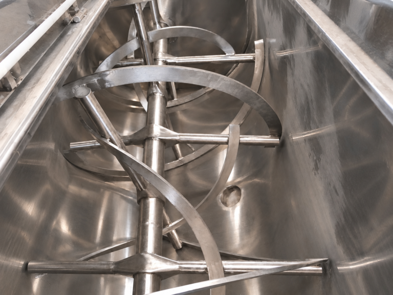
Double-Helical Counter-Flow Ribbon Assembly

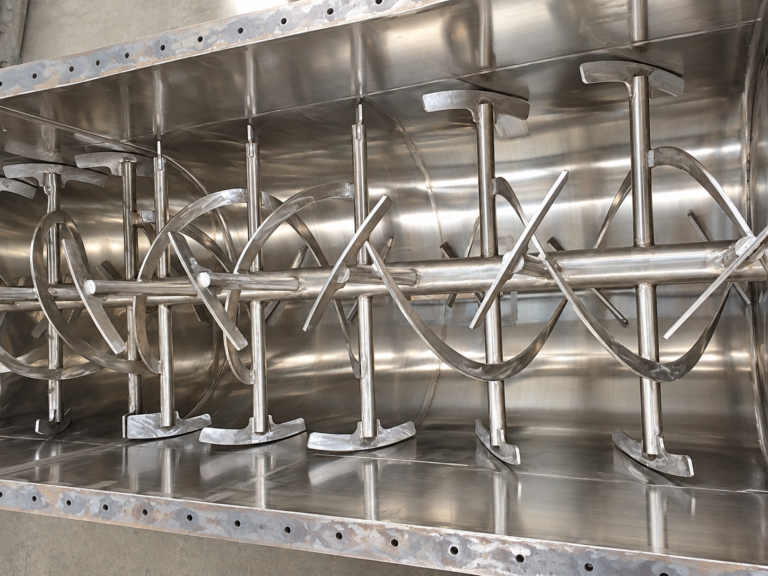
Inner and outer continuous helical flights mounted on a heavy-duty center shaft. The outer ribbon conveys ingredients toward the central discharge, while the inner ribbon sweeps material outward to the endplates, creating high-efficiency fluidization, counter-current convection, and rapid axial dispersion without shearing polymer chains.
Precision U-Shaped Trough with Zero Dead-Zone Design

One-piece U-shaped vessel fabricated with continuous inner welds ground smooth to Ra ≤ 0.8 µm. Precision ribbon-to-wall radial clearances minimize stagnant unmixed pockets, ensuring consistent batch homogeneity and rapid cleanability during color and formulation changeovers.

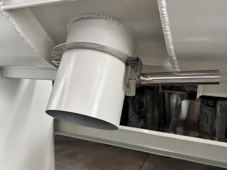
Flush Bottom Discharge Spout with Flanged Outlet

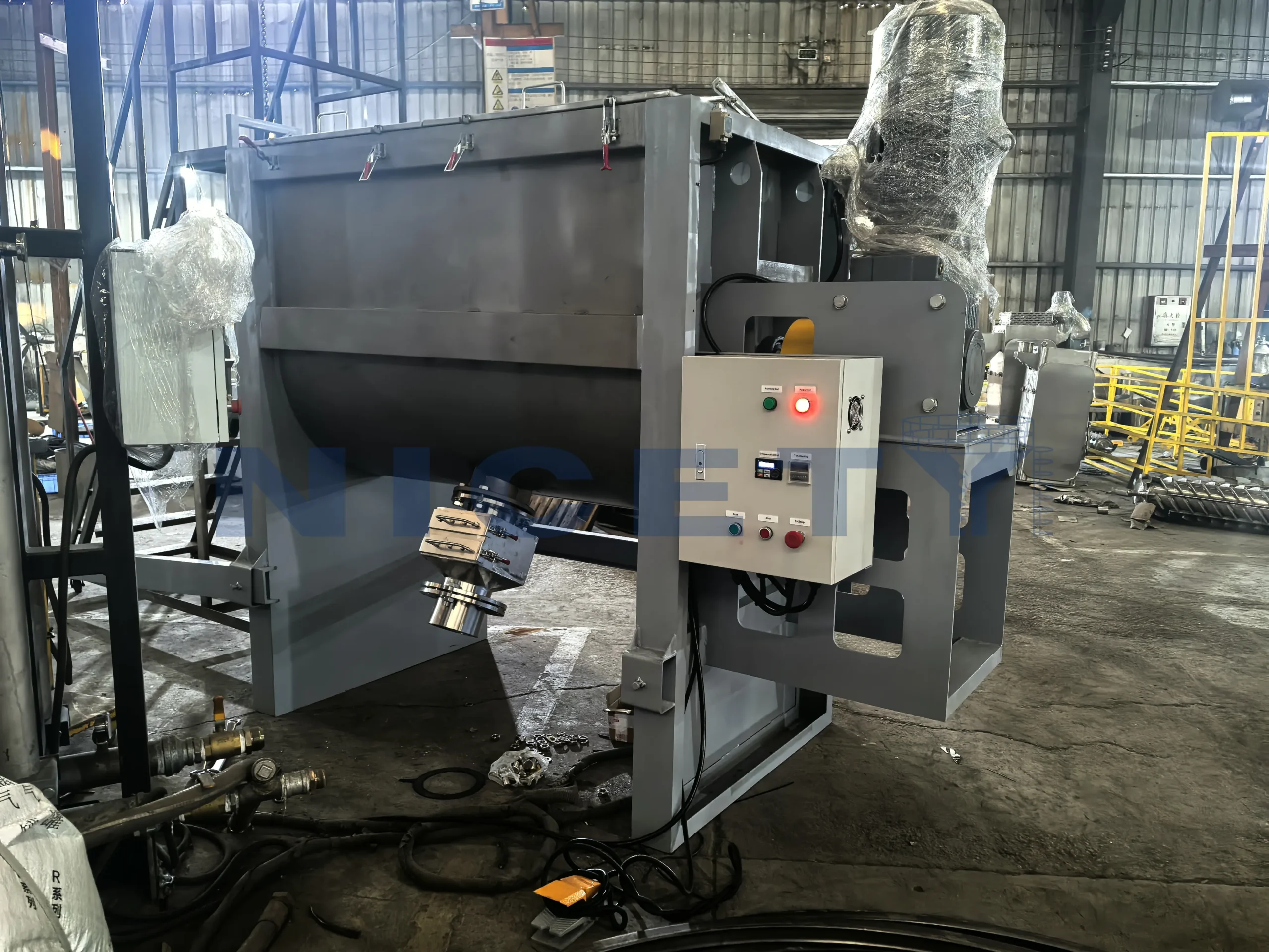
The outlet is set at the centre of the trough with the opening contoured to the trough radius, so no ledge is left for material to rest on. The spout is flanged to suit the container or conveyor you discharge into, and the discharge clearance is confirmed against the bin, IBC or mobile container actually used on site. The gate is hand-operated on the standard build and available pneumatically where the line needs faster emptying.

Safety Interlocked Inspection Cover & Loading Ports

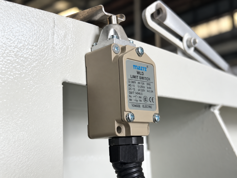
Top cover features sealed pneumatic gas-spring assist inspection hatches protected by safety interlock limit switches. The blender automatically cuts drive power instantly when covers open, ensuring complete operator safety during cleaning, inspection, and maintenance.

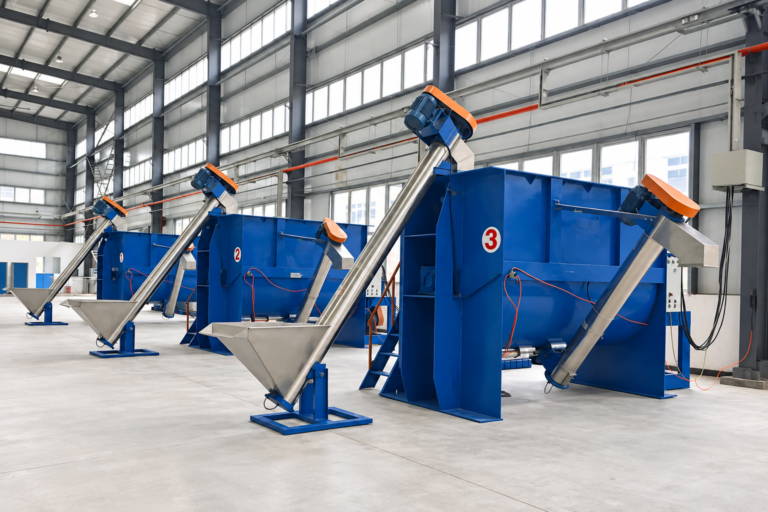
Screw-Conveyor Charging with Adjustable Feed Rate

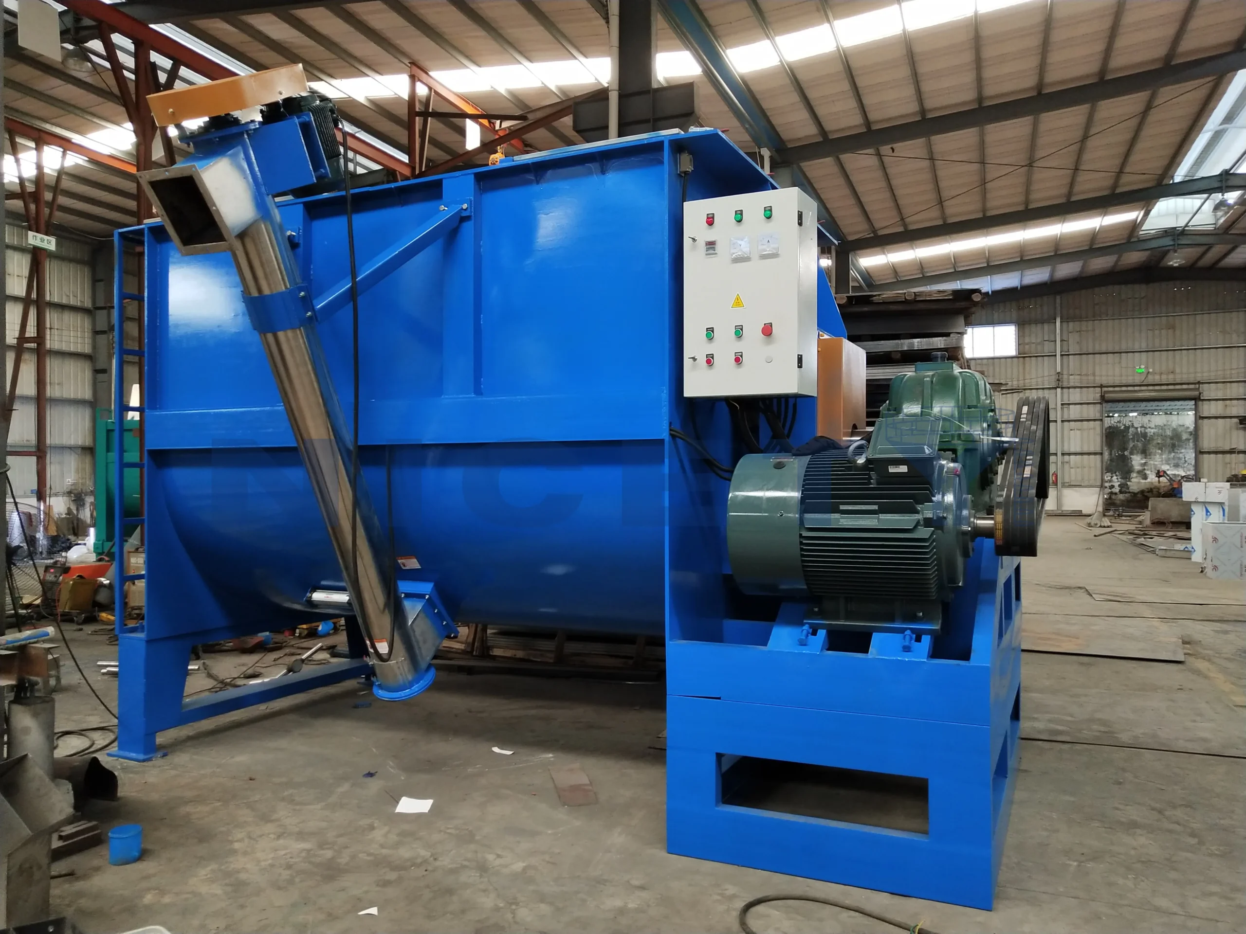
Prepared for Screw-Conveyor Charging The top cover inlet is flanged and positioned so a screw conveyor or screw feeder can be connected directly, and the inlet size is confirmed against the conveyor finally chosen for the line. The blender itself is supplied ready for that connection rather than with a fabricated hopper.

Material and process

Where it fits — and where it does not

Read the conditions together: a machine is selected for the material and the output, not from its name alone.

Suitable materials and conditions

Optimized for free-flowing polymer pellets, virgin resins, recycled regrind flakes, color and additive masterbatches, and mineral powders (such as calcium carbonate, talc, barium sulfate, and flame retardants). The dual counter-flow ribbon geometry ensures rapid, convective macro-mixing across divergent bulk densities (0.25 to 1.6 kg/L) and particle diameters (20 µm powders up to 10 mm flakes/pellets).

Particularly suited for formulations sensitive to friction-induced temperature rise, including soft elastomers (TPE, TPU, TPV, EVA), PVC dry-blends, hot-melt adhesives, and engineering plastics pre-compounded with lubricants or liquid bonding agents. Batch working capacities range from 300 liters to 3,000 liters per cycle.

Limitations and when it does not apply

Convective solid-solid batch mixer and homogenizer; not a high-intensity disperser or plasticizing reactor. Operating boundaries include:

  • No melt shear: Provides macro-mixing without polymer melting; pigment micro-dispersion and plastication take place in the compounding extruder.
  • Liquid additions limit (<1%–3%): Higher liquid ratios require specialized high-speed chopper blades or paddle agitators to prevent balling and caking.
  • Cohesive damp cakes: Tacky or highly cohesive sludges exhibit poor bulk flowability and require customized paddle agitator profiles.
  • Abrasive mineral wear: High-loading abrasive minerals (quartz, silica, chopped glass fibers) require tungsten carbide hardfacing and replaceable wear liners.

Feed condition and requirements

Accepts free-flowing virgin polymer pellets, post-consumer / post-industrial regrind flakes, masterbatch granules, micronized additives, and mineral powders (CaCO3, talc, flame retardants, stabilizers). Charging can be performed via top manual bag-dump stations with integrated dust filtration hoods, flexible bulk bag (FIBC) unloaders, or pneumatic conveying vacuum receivers.

Input raw ingredients must be free of metallic tramp contamination, oversized agglomerates exceeding ribbon clearances, and free-standing moisture that could cause severe powder cake formation inside the trough.

Output condition and boundaries

Delivers a uniformly distributed, homogeneous dry batch with minimal particle attrition and no thermal degradation. Discharges via the bottom central gate directly into mobile transfer bins, intermediate bulk containers (IBCs), pneumatic dense/dilute phase conveying pick-up adapters, or surge hoppers positioned above loss-in-weight compounding extruders.

Clean batch discharge is achieved within 60 to 180 seconds, leaving negligible residual holdup in the bottom trough.

Throughput

Capacity range

Read a figure together with the basis below it: the same machine reaches different numbers on different materials.

300–10000 L (batch working volume)

Basis for the capacity figures

Figures denote the effective working volume (typically 40% to 70% of the total trough volume) required for optimal cross-flow fluidization and turnover. Usable batch weight depends on material bulk density, component proportions, and flow characteristics. Highly filled powders fill the working volume at different mass loadings than light virgin pellets or regrind flakes.

Models

Models in this range

The figures are the reference values entered for each model. The model for your line is confirmed against your material and output before it is quoted.

NC-W1000 Sanitary Ribbon Blender for Masterbatch & Additive Pre-Blending

Delivered a 1,000L working capacity horizontal ribbon blender for an additive compounding facility. Configured with mirror-polished SUS304 contact surfaces and an air-purged bottom discharge gate, the unit delivers gentle, convective macro-mixing of fragile pellets and pigment powders within 4–6 minutes without frictional melting.

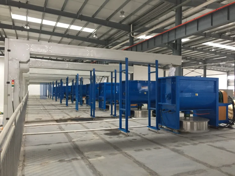
Centralized Multi-Unit Ribbon Blender Array for Engineering Plastics Compounding

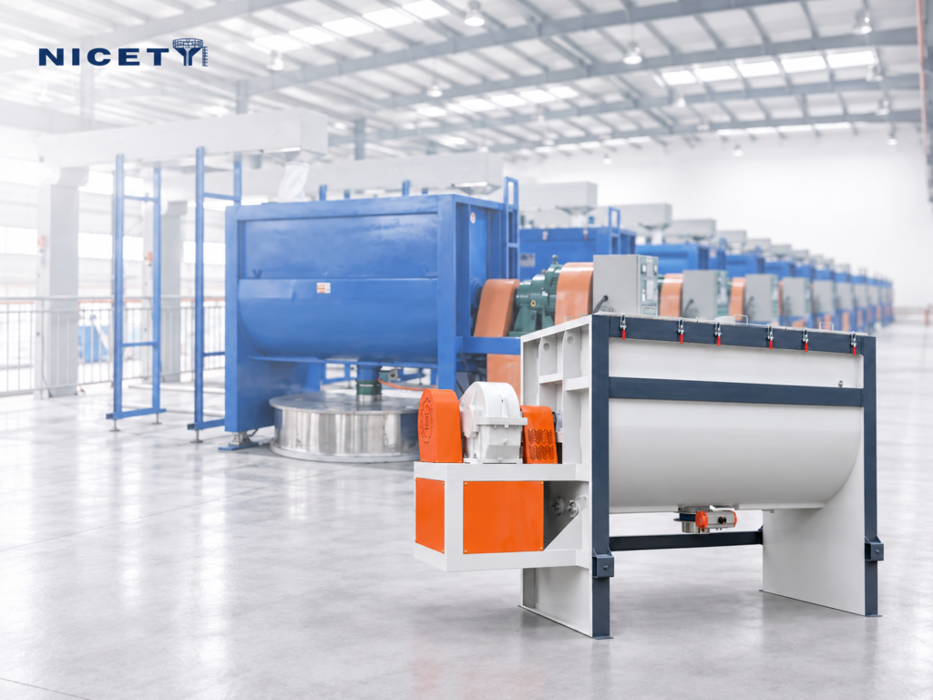
Supplied an array of multi-ton horizontal ribbon blenders for a large-scale engineering plastics compounding workshop. Operating in continuous batch rotation, the units feed multiple twin-screw extrusion lines, ensuring consistent bulk density and zero lot-to-lot color deviation across high-capacity compounding operations.

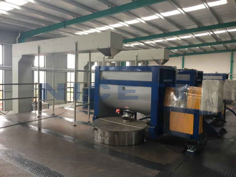
NC-W3000 Heavy-Duty Ribbon Blender with Feeding Mezzanine for Recycling Flakes

Engineered and commissioned a heavy-duty 3,000L ribbon blender installed on an elevated mezzanine platform for a post-consumer plastics recycling plant. Equipped with reinforced helical ribbons and pneumatic vacuum loading interfaces, the system thoroughly homogenizes recycled flakes across divergent bulk densities (0.3–0.9 kg/L) before extrusion.

Scroll the table sideways to read every column →

Model Capacity range Rated power Dimensions Heating power (optional)
NC-W200 0.5 Ton/Batch 3 kW 2000 × 750 × 1500 mm 9Kw
NC-W300 1 Ton/Batch 4 kW 2400 × 800 × 1650 mm 12Kw
NC-W500 2 Ton/Batch 5.5 kW 2200 × 1100 × 1800 mm 12Kw
NC-W1000 3 Ton/Batch 11 kW 2900 × 1350 × 2200 mm 24Kw
NC-W1500 4 Ton/Batch 11 kW 3300 × 1350 × 2200 mm 24Kw
NC-W2000 5 Ton/Batch 18.5 kW 3400 × 1450 × 2400 mm 32Kw
NC-W2500 6 Ton/Batch 22 kW 3600 × 1450 × 2400 mm 32Kw
NC-W3000 8 Ton/Batch 30 kW 4200 × 1600 × 2600 mm 36Kw
NC-W5000 10 Ton/Batch 45 kW 4500 × 1950 × 2800 mm 48Kw

Scope of supply

What is included, and what is not

The quotation states the scope for the confirmed configuration; the groups below describe how a supply is normally split.

Included as standard

  • Heavy-duty horizontal ribbon and center shaft assembly Double-helical counter-flow design with balanced outer and inner flights, dynamic balance verified, mounted and aligned in the trough prior to factory testing.
  • Full SUS304 stainless steel product contact surfaces Trough vessel, endplates, top covers, ribbons, and discharge door polished to smooth industrial finish (Ra ≤ 0.8 µm) for clean material release.
  • Heavy-duty helical-bevel gear motor drive Direct-coupled or chain-driven high-efficiency gear motor engineered with high starting torque factor for loaded starts.
  • Top cover with safety-interlocked inspection hatches Fitted with gas spring opening struts, mechanical safety switches, flanged charging ports, and dust extraction connection flange.
  • Floor-standing / machine-mounted electrical control panel Equipped with main isolator, motor circuit breaker, soft-starter or inverter (VFD), forward/reverse jog, emergency stop, and digital mixing cycle timer.

Optional items

  • Weighing frame Load cells under the trough for batch weighing.
  • Big-bag loading station For components delivered in big bags.
  • Pneumatic discharge gate In place of the manual slide gate.
  • Trough and ribbon metallurgy SUS304 standard; SUS316L for corrosive formulations; wear-resistant liners (Hardox or tungsten carbide coating) for abrasive mineral fillers or glass fiber regrind.
  • Shaft seal configuration Braided Teflon packing gland standard; multi-stage air-purged stuffing boxes or split mechanical seals available for ultra-fine powders and frequent recipe washdowns.
  • Heating / cooling jacket Dimpled or double-walled jacket on the trough exterior for circulating hot oil, steam, or chilled water to manage temperature during mixing.
  • Integrated batch weighing frame High-precision load cell modules mounted under the machine support legs with digital batch summing indicators.

Not included

  • Civil engineering and anchor foundations Floor reinforcement, anchor bolts, and foundation slabs on the customer's site.
  • External electrical cabling and pneumatic piping Power feeder cables to the machine disconnect switch and compressed air supply lines up to the air preparation filter-regulator unit.
  • Upstream feeding and downstream conveying systems Vacuum loaders, screw feeders, big-bag discharging stations, and discharge surge bins unless explicitly quoted as part of an integrated turnkey system.
  • Exhaust and central dust extraction ducting Plant-side dust collection fans, filter bags, and interconnecting ductwork outside the blender inlet flange.

Installation planning

Utilities, interfaces and site readiness

These are the connections the machine and the line around it have to agree on before the layout is fixed.

Utility requirements

Power supply
380 V / 415 V / 460 V / 220 V (customizable), 50/60 Hz, 3-phase AC.
Water
Not required for standard dry blending; cooling/heating jackets (if configured) require dedicated chilled water, steam, or thermal oil circuits.
Compressed air
0.5–0.7 MPa (5–7 bar), clean, dry, oil-free instrument air for pneumatic discharge gate and optional air-purged shaft seals (consumption: approx. 0.1–0.3 m³/min during actuation).
Exhaust and ventilation
Passive breathing breather filter on top cover; central dust collection connection (DN150–DN200) recommended when charging fine powders to maintain negative pressure and prevent fugitive dust.
Other notes
Electrical ratings vary by batch volume and blend bulk density. Upstream feeding equipment and downstream discharge conveying systems require separate utility supplies.

Interface requirements

Mechanical: Bolted baseplates anchored to a level foundation floor or elevated mezzanine steel structure; standard round/square flanged charging ports (DN200–DN300) and central bottom discharge flange (DN150–DN250) compatible with slide valves, butterfly valves, or flexible bellows.

Electrical & Automation: Three-phase main power connection to the IP54/IP55 floor-standing or machine-mounted control cabinet. Control terminals provide dry potential-free contacts for remote Run/Stop status, cycle completion, safety interlock trips, and handshake interlocks with upstream feeding systems and downstream buffer receivers.

What the customer prepares on site

The buyer provides a reinforced level concrete floor engineered for static and dynamic machine operating loads, unhindered access corridors for cleaning and shaft/bearing maintenance, and main power supply terminated at the local electrical control panel. Upstream charging infrastructure (overhead hoists, big-bag discharge frames, or pneumatic receiver mounts) and downstream discharge hoppers/surge bins are coordinated to the agreed machine centerline dimensions.

Selection

How to choose a model

Work through what you already know. The rest is settled in the conversation, not before the first message.

Blender selection should be based on effective working volume, bulk density, and target batch cycle time rather than gross trough volume alone:

  • Calculate Working Volume: Size the machine so your intended batch weight occupies between 40% and 70% of the gross trough volume. Underfilling (below 30%) fails to establish the counter-flow ribbon circulation, while overfilling (above 80%) prevents top-layer expansion and cross-folding, causing prolonged cycle times and poor uniformity.
  • Motor Drive Sizing: Dense mineral masterbatches (bulk density > 0.8 kg/L) exert substantially higher starting torque than light unfilled pellets or foam regrind (0.3–0.5 kg/L). Select gear motor ratings accordingly to ensure reliable loaded-start capability.
  • Material Selection: Standard plastic compounding uses polished SUS304 for all contact surfaces. Opt for SUS316L if running acidic flame retardants or corrosive additives, and specify abrasion-resistant Hardox/bimetallic wear plates when processing glass fiber compounds or abrasive minerals.
  • Discharge Method: Select manual slide gates for low-frequency multi-recipe job shops; specify pneumatic contoured flap gates for automated lines demanding fast discharge cycles under 2 minutes.

Information we need from you

  1. 01 Blend components and formulation ratio Specific types of polymers (virgin, regrind, elastomer), mineral fillers (CaCO3, talc, TiO2), and functional additives (antioxidants, lubricants, pigments) along with their mass or percentage proportions.
  2. 02 Bulk density and particle size distribution Bulk density (g/cm³ or kg/L) and particle characteristics (microns/mesh for powders, mm for pellets/flakes) for each raw ingredient to calculate working volume, motor load, and ribbon clearance.
  3. 03 Target batch size and cycle requirement Required batch weight or volume (kg or liters per batch) and desired cycle time/hourly throughput (batches per hour or kg/h) to size the blender and determine discharge automation.
  4. 04 Liquid addition and thermal constraints Details of any liquid additives (e.g., mineral oil, plasticizer, silane coupling agent) including percentage, viscosity, and temperature sensitivity of polymers (such as low melting-point EVA or soft TPE/TPU).
  5. 05 Installation footprint and plant utilities Available floor area, ceiling headroom, loading height limits, feeding method (manual hopper, vacuum loader, or big-bag station), and site electrical supply (voltage, frequency, and phase).

Request a Quote A model name, a material or a drawing is enough to start.

Photos and videos

The machine itself

Videos

Next step

Request a Quote

Tell us the material, the process and what you need to achieve. Technical details can be completed later together with our sales team.

Request a Quote
Request a Quote